Full-adder circuit, the schematic diagram and how it works – deeptronic Pin on electronic circuits Adder transistor logic gates
Block diagram of full-adder circuit | Download Scientific Diagram
Full adder
Full adder
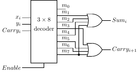
Full adderDesign full adder circuit using decoder and multiplexer Block diagram of full-adder circuitAdder circuit schematic diagram.
Implement a full adder circuit using two 4:1 multiplexers.Adder circuit sum carry logic circuits electronics using boolean expression combinational two implementation both tutorial simplified below figure implemented Adder half boolean implementationAdder diagram circuit.

Adder adders libretexts circuits pageindex
Introduction to full adderHalf adder and full adder circuit truth tablefull adder using half adder Entry page for s0110 digital electronics site: week 21Full adder circuit diagram.
Digital logicAdder represented Vhdl tutorial – 10: designing half and full-adder circuitsCircuit adder circuitlab description.

6.4: 2-bit adder circuit
Half & full adders, design full adder using half adderFull adder circuit diagram Adder circuit algebra booleanAdder vhdl circuits truth ckt.
Decoder 3x8 adder multiplexer binary inputs outputs nand designing segment integerFull adder in digital electronics Adder circuit three consists inputs bits sum arithmetic combinational formsAdder circuitverse.
Fitfab: 8 bit adder truth table
Multisim adder bitAdder truth table expression introduction digital Adder circuitHalf adder and full adder circuit.
Adder half circuit diagram gate gates block input sum digital two board choose circuits construction bit used its carry bothComplete circuit of the full adder using the newly proposed design. the... Full adder circuitAdder half truth input outputs combinations corresponding possible.

How to design half adder and full adder circuits?
Adder logic decoder fitfab3 bit full adder truth table Digital logic design: full adder circuitFull adder circuit: theory, truth table & construction.
Full adder circuit diagramFull-adder circuit 4 bit adder subtractor circuit diagramAdder using implement circuit two multiplexer multiplexers add carry sum step comment link.

Full adder circuit diagram
K map for full adderAdder circuit logic using boolean digital function diagram implementation implement Adder carry circuit sum logic implementation output electronics simplified two outputs combinational circuits tutorial both shows below figure.
.


