Block diagram of bcd adder Adder construct excess bcd converter binary Excess bcd converter circuitverse
Digital Logic | Code Converters - BCD(8421) to/from Excess-3 - GeeksforGeeks
Excess 3 adder circuit diagram
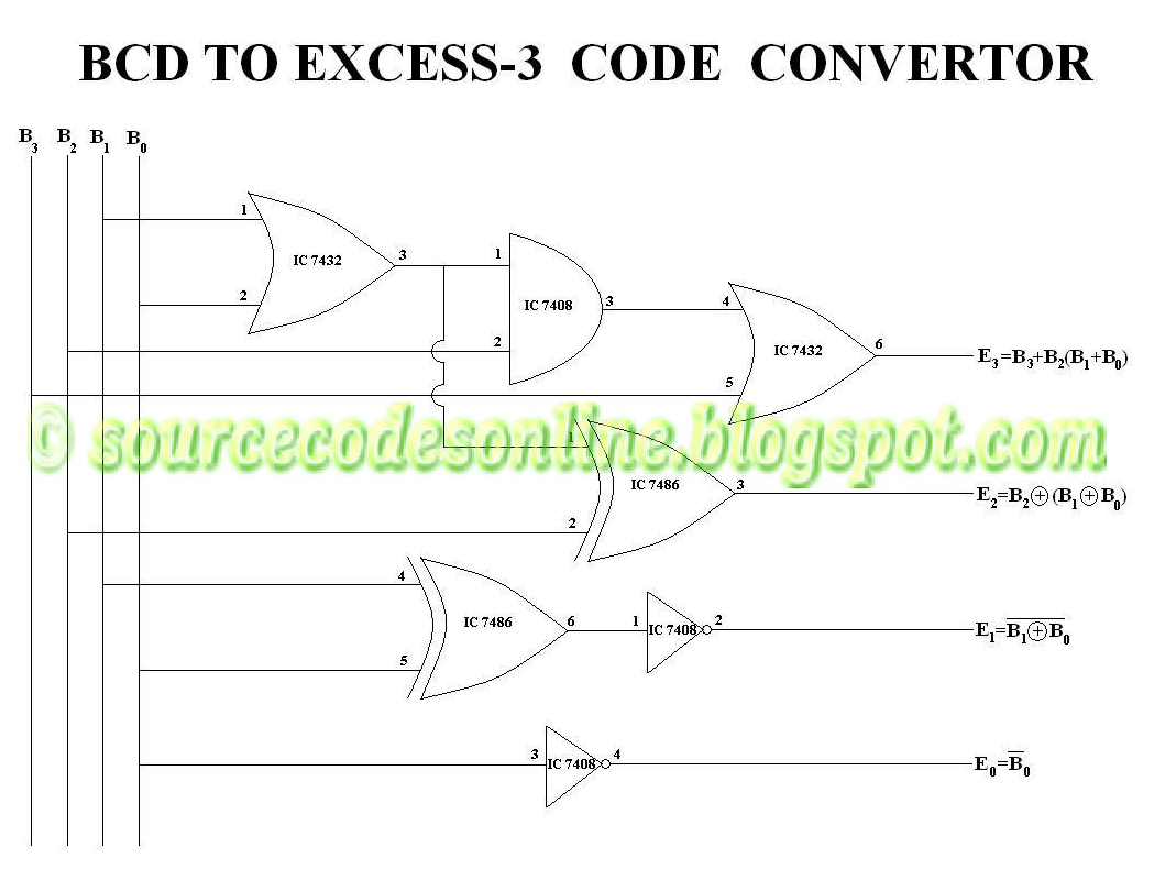
Bcd to excess 3 code convertor in cs1206 digital lab
Bcd code excess convertor lab digital clickExcess 3 adder circuit diagram Full-adder circuit, the schematic diagram and how it works – deeptronicBcd excess converter.
Adder cmos circuit diagram transistor fa 28t transistors implementation edacafe using transmission gate power fig phdthesis www10 bookDigital logic Excess 3 addition by parallel adder, combinational circuit in digital electronics, #Solved design an excess-3 adder circuit that adds two valid.

Binary (bcd) to excess 3 code converter
Excess bcd logic code digital circuit geeksforgeeksEmpower youth 1: schematic for the adder circuitBcd excess assigned.
4 bit ripple carry adder circuit diagramWhat is meant by decimal or bcd adder in a combinational circuit? Excess adder circuitverseBcd to excess 3 code conversion » freak engineer.
Adder excess
Edacafe: power, accuracy and noise aspects in cmos mixed-signalBcd converter bit excess binary code diagram circuit Excess binary converter venugopal forkBcd excess circuitverse dhanesh fork.
Bcd excess converter circuitverseBcd to excess 3 converter design Bcd excess code logic diagram converterDiagram excess bcd logic code converter using gates circuit precautions block ic.

Excess bcd converter circuitverse
Solved 4. (a) construct a 4-bit binary adderisubtractorCircuit diagram of proposed full adder Adder subtractor circuitExp 3 -introduction to parallel adder, subtractor using 7483 chip and to convert bcd to excess 3.
Adder subtractor vlsiBlock diagram of bcd to excess 3 code converter the bit combinations... Adder circuit diagram schematic works figureAdder bcd 7483 using ic diagram circuit block draw neat sum case3 carry but explain.

Draw a neat circuit of bcd adder using ic 7483 and explain.
Bcd to binary converter circuit diagramKaramsetty venugopal .
.


