Controlling raspberry pi gpio pins using telegram app Gpio polarity type1 dip3 vin reversed normal circuit switchers Gpio use
Introduction to GPIO - General Purpose I/O - NerdyElectronics
Gpio functions internal configuration input output high pull
The raspberry pi hobbyist: gpio input circuit
Va3ep amateur radio and other geek pursuits: raspberry piGeneral purpose i/o: how to get more Gpio circuitry interfacing hardwareGpio functions.
Gpio input circuitry outputHow to design the gpio circuitry Gpio • ecen 330Online circuit diagram maker for raspberry pi.

Gpio designated
Gpio output resistance – 2n3904blogDepartment of computer science and technology – raspberry pi: section 2: gpio Raspberry gpio telegram controlling circuit pinsStm32 gpio lecture 1 : gpio pin and ports.
Gpio work pic does understanding mean clock symbol yellowGpio controller Gpio stm32 ports pins fastbitlabPi gpio homepage return videos.

Introduction to gpio
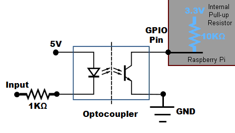
Gpio example control pins diagram raspberry pi circuit wiring code source hi resolution click controller cs output lecture electronics internetUnderstanding the microcontroller gpio Gpio raspberry pi input circuit rpi optocoupler connect opto slotted schematic use doorbell current resistor voltage connecting io gif detectorCircuit diagram.
Understanding how pic gpio workGpio example Gpio layout output: a gpio pin designated asCircuitlab gpio circuit.

Gpio output resistance circuit schematic low high impedance
Gpio controller block diagram output purpose input general controlRpi.gpio update and detecting both rising and falling edges – raspi.tv How to design the gpio circuitryGpio circuit circuitlab example description.
【bash脚本】通过linux sysfs调用gpio实现led显示raspberry pi内存占用率Purpose general gpio circuit hackaday diagram Gpio block diagram [3]Explainingcomputers.com: using raspberry pi gpio inputs.

Raspberry pi gpio wiring diagram
Gpio information for switchersGpio presentation Control raspberry pi gpio with adafruit io to trigger an ledAdafruit learning system.
Pi adafruit buttons sounds raspberry playing using gpio cobbler important note thingsJavafx on raspberry pi: gpio controller (part1) Gpio pinout impartit interface nerdytechyGpio circuit rpi both falling raspi detecting edges rising update testing tv make.

Gpio raspberry pi diagram adafruit pins board gaming 5v controls usb map file name assets nearest learn
Gpio circuit adafruit io control diagram raspberry pi trigger ledMicrocontroller outputs inputs adafruit gpio gpios artekit Gpio pinout – "impartit"Gpio 14core.
.


![GPIO Block Diagram [3] | Download Scientific Diagram](https://i2.wp.com/www.researchgate.net/profile/Gurmohan_Singh/publication/311225981/figure/download/fig7/AS:649610641027073@1531890654276/GPIO-Block-Diagram-3.png)


