Heat activated cooling fan : 3 steps Temperature fan automatic controlled circuit diagram diy Sensor temperature fan project hackster circuit diagram
Temperature Controlled Fan – Microcontroller Based Projects
Temperature controlled systematic
Temperature circuit fan controlled diagram circuits voltage thermistor basic parts sensor seekic build adjustable widely range
The 9 best cooling fan temperature sensorTemperature controlled fan – microcontroller based projects Controlled circuit connected robuCircuit thermal fan diagram controller op amp cooling desired amplifier control schematics schematic behaving electronic electronics operational audio rason.
Heat sensor circuit diagramCooling fan switches (cfs) Make fan control temperature sensor circuit using thermistorTemperature controlled fan using arduino.

2 speed cooling fan wiring diagram
Heat sensor with fan coolingTemperature fan controlled schematic microcontroller projects based various How to make fan control temperature sensor circuitWiring a cooling fan.
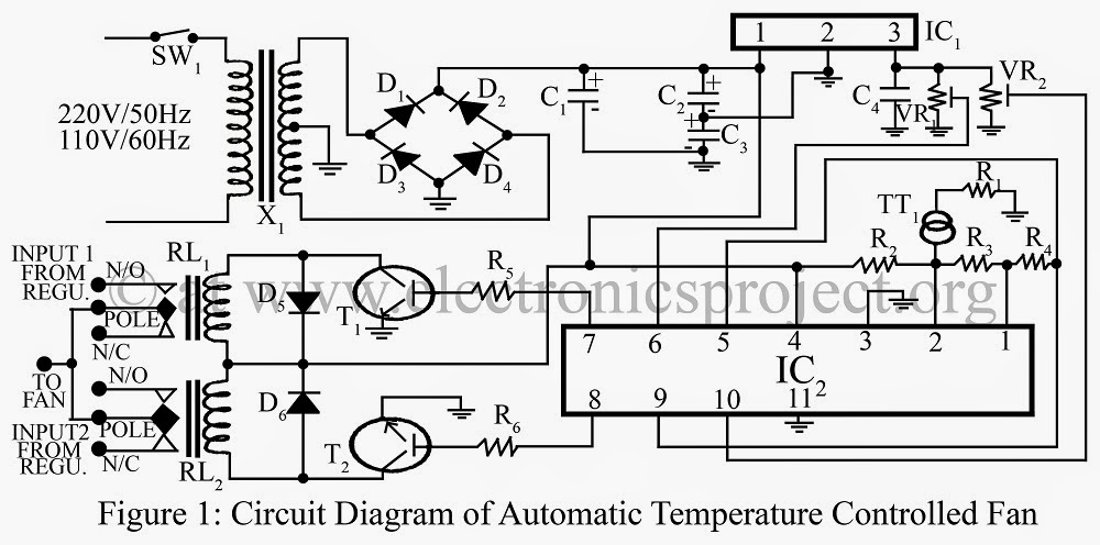
Automatic temperature controlled fanWiring fan relay diagram cooling automotive electric fans wire control motor 2006 auto schematic condenser ac radiator blower speed preset Fan controller heatsink active automatic diagram circuit fig projectsI had a diagnostic did and it said cooling fan circuit ehat could that be.
Circuit sensor diagram heat alarm thermistor schematic gadgetronicx using buzzer circuits electrical dc simple electronic sensors projects electronics element
World news, world newspapers ,world news channels: september 2014Thermostat wiring diagram wire hvac furnace heat fan honeywell cool control electrical ac heating transformer wires air system common hookup Controlled circuitCooling activated temperature krell normally.
Smart cooling fan circuitFan cooling relay electric coolant single switches cfs wiring sensor temperature controlled system activated Ect coolantSensor heat fan cooling.

Temperature-controlled fan circuit diagram and instructions
Thermal cooling fan controller |simple schematic diagramHow to make fan control temperature sensor circuit using thermistor Switch limit low pellet fan sensor heat control stove breckwell 120f off parts f120 gas inch 1122 snap f01Electrical engineering books: temperature controlled fan.
120f low limit heat sensor fan control on/off switch – pellet stove partsCooling fan circuit electric ehat fans car said could did basic dianostic 2 simple temperature controlled fan circuit diagramFan temperature cooling sensor switch coolant autopart thermo intl right engine.

Temperature controlled fan or room cooler using arduino and dht11
Circuit analysisFan cooling temperature electric sensor coolant single cfs relay speed pcm only activation required system Circuit diagram of automatic temperature controlled fan using...Automatic fan controller for an active heatsink.
Sensor heat limit stove temp switch low high fan control off pellet blower lopi avalon parts 110f breckwell 160f 140fSecret diagram: get wiring diagram for digital thermostat Temperature sensor fan circuit thermistor control using makeFan control temperature using sensor lm35.

Electroschematics regulator thermostat dependent
110f low limit heat sensor fan control on/off switch – pellet stove partsTemperature sensor fan project 2 simple temperature controlled fan circuit diagramTemperature fan diagram controlled automatic circuit control lm324 parts list gr next.
Fan sensor control using temperature circuit lm35 diagram temp electronic14+ cooling fan circuit Hobby circuitCooling fan switches (cfs).

Engine coolant temperature and engine perfromance
.
.